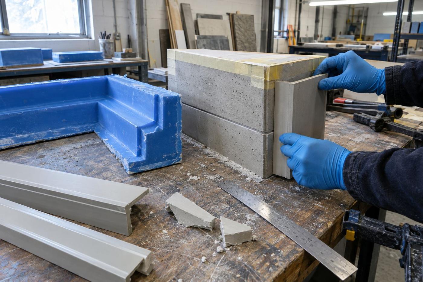
The relief is designed, not off-the-shelf
The architect has drawn a specific relief. A stock formliner won't match it. A bespoke silicone or polyurethane tool built from the architect's drawing will.
Architectural cladding · Bespoke tooling
Bespoke silicone and polyurethane moulds for façade cladding panels, cornices, spandrels, string courses and feature elements. We come in early with the architect and the panel manufacturer so the tool suits the drawing, not the other way round.
When it fits
The architect has drawn a specific relief. A stock formliner won't match it. A bespoke silicone or polyurethane tool built from the architect's drawing will.
The relief continues from panel to panel, so splice lines and panel joints have to be co-ordinated. We do that on the drawing before the tool is poured.
Architects and specifiers often need to see a written material spec before they'll approve the tool. We supply one as standard.
Client, architect, panel manufacturer and us all present at first-off. It's easier to bring us in early than to redesign the tool after the meeting.
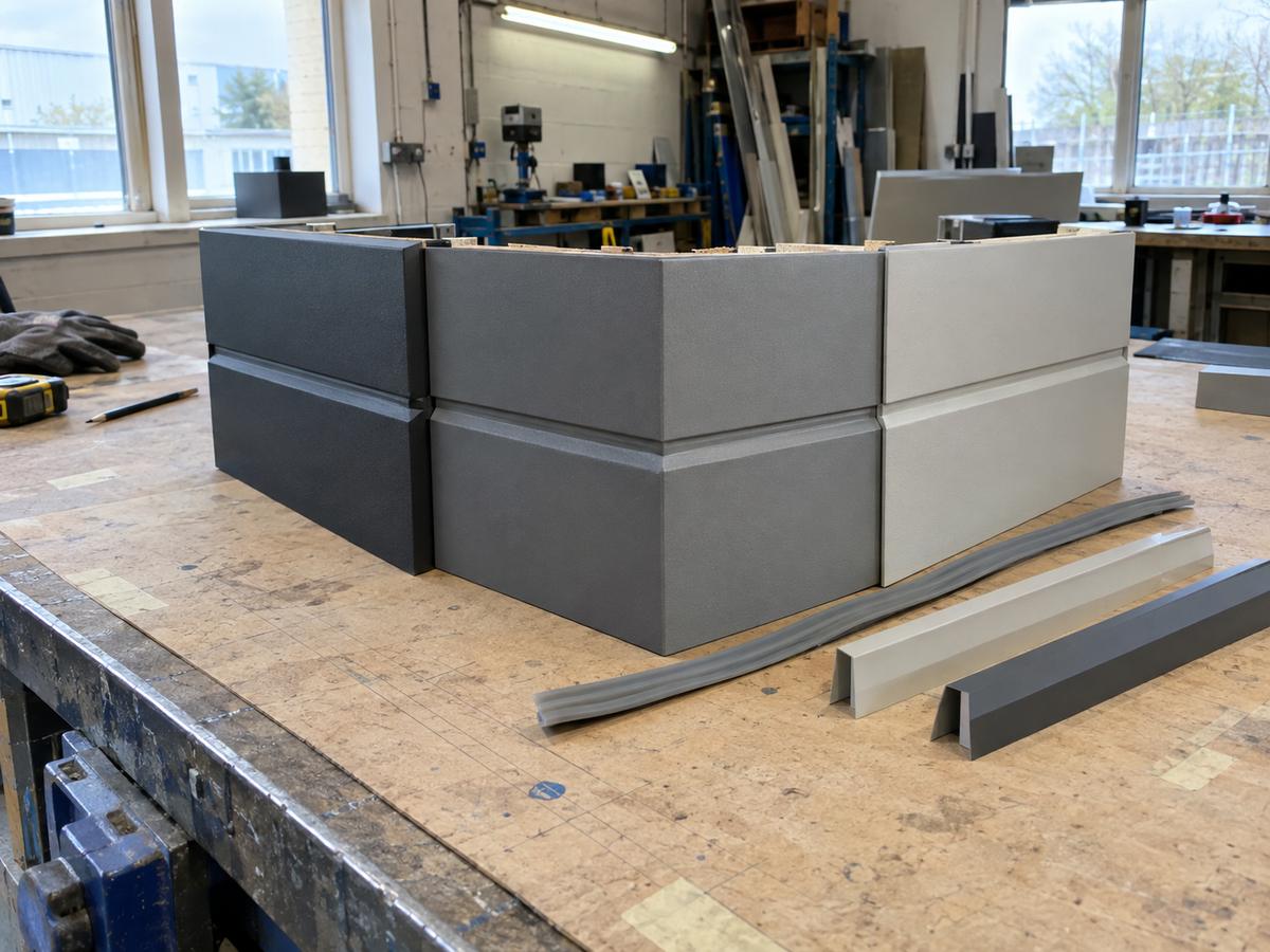
The choice
The best cladding tools are the ones where we've been in the conversation from concept stage. We can tell an architect early which reliefs will demould, which will need special release, and which will need reshaping to avoid a permanent visible splice line. That's a lot cheaper than finding out at first-off.
For a specifier writing a spec, we'll supply a technical sheet describing the silicone or polyurethane grade, its temperature range, its expected working life for the pour count and mix specified, and its release compatibility. Nothing dressed up.
For a panel manufacturer, we work off your bed sizes, your release regime, and your handling equipment. The tool is designed to fit the way your yard already works, rather than requiring you to change process for it.
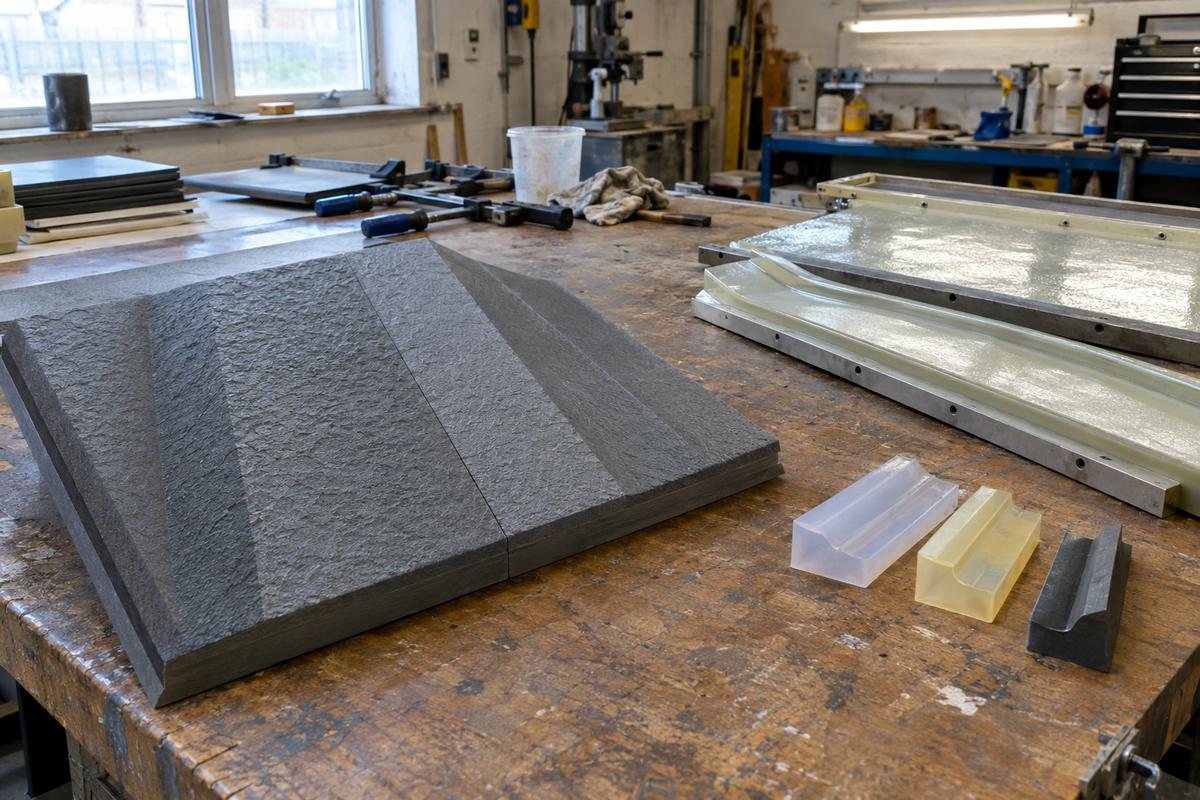
What we need
Elevation drawing with the relief marked, panel drawings with sizes, joint layout across the façade.
Bed size, mix, release regime, stripping method.
Determines material grade and whether we need parallel tools to hit programme.
Architect, engineer, client, specifier. We can attend if that helps.
The honest bit
Cladding jobs where we're brought in after the design is frozen are always harder than jobs where we've been in the room since concept. Not because we can't build the tool — we can — but because the design will occasionally contain a feature that's expensive to mould and cheap to redraw, and by the time it's frozen the redraw is off the table.
We'll be honest at every stage about which parts of the design are cheap to mould and which are expensive. The architect keeps the design lead; we just make sure they're spending mould budget where it gives them the visual, not where the drawing accidentally happens to require it.
Splices will exist. They're the seams where sections of the tool meet, and on a large panel with a repeating relief they're inevitable. We can put them where they read least — often at the panel joint — but we can't make them invisible.
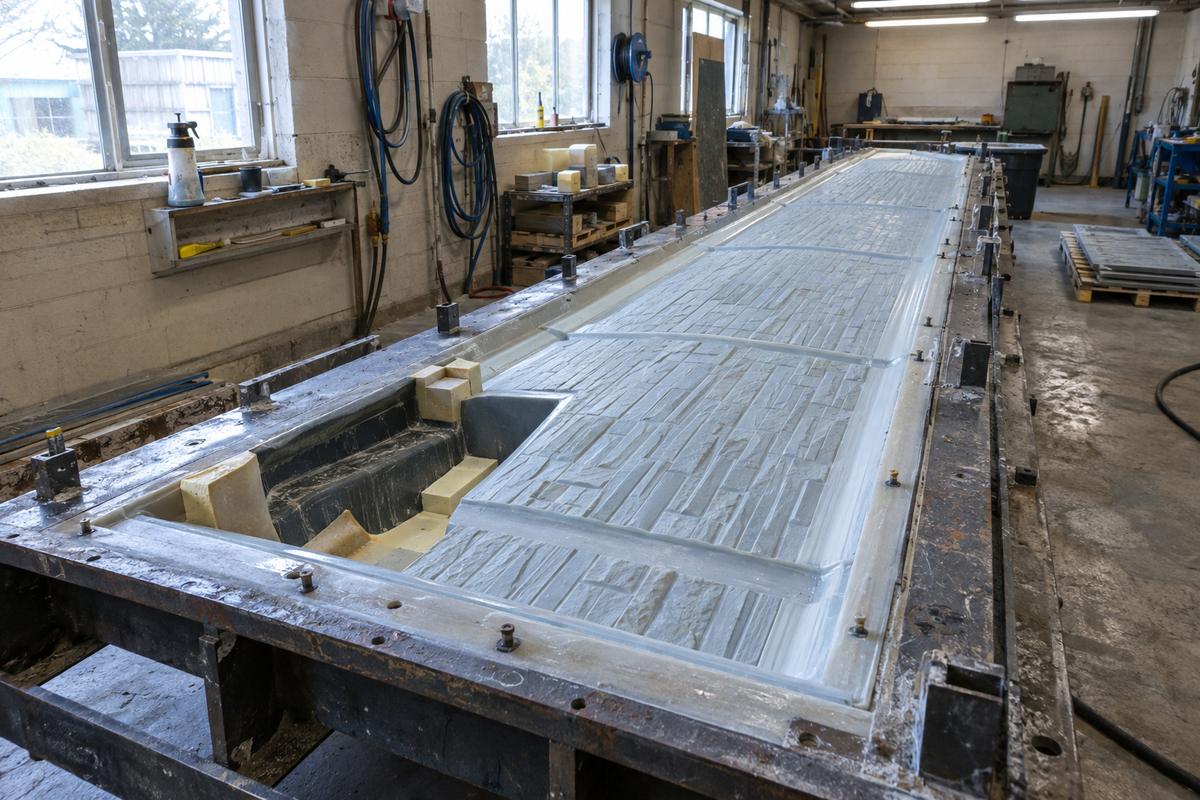
Drill down
Each one has its own page with the detail we'd normally cover on the first call.
Related
At a glance
Planning liners across a wall
Swipe to see the whole diagram
From sample to finished cast
Swipe to see the whole diagram
Get in touch
One photograph tells us what surface you're chasing, and one line about the mix tells us what silicone or polyurethane will survive it.
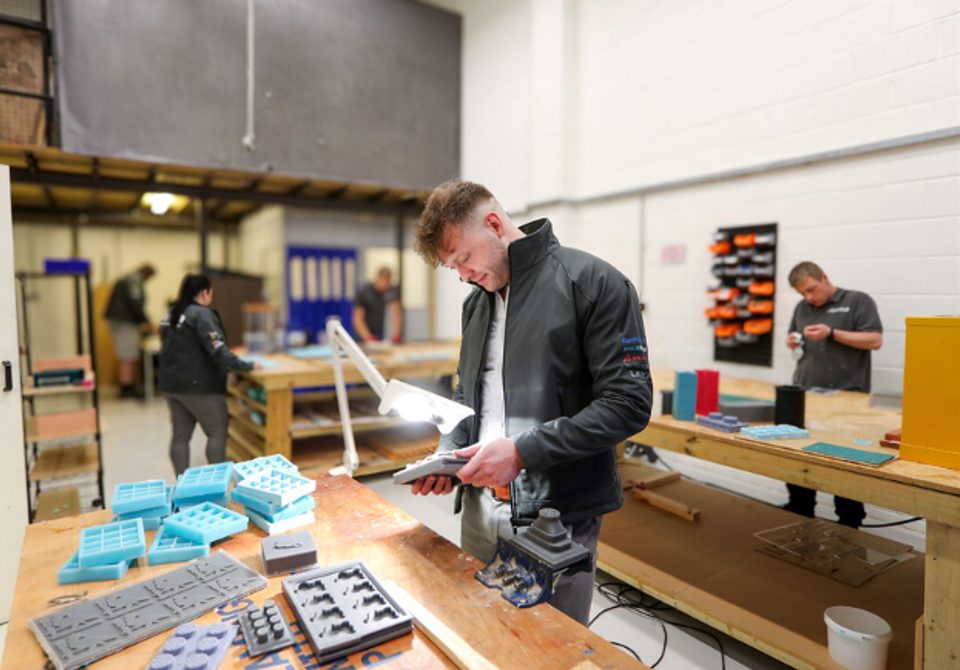
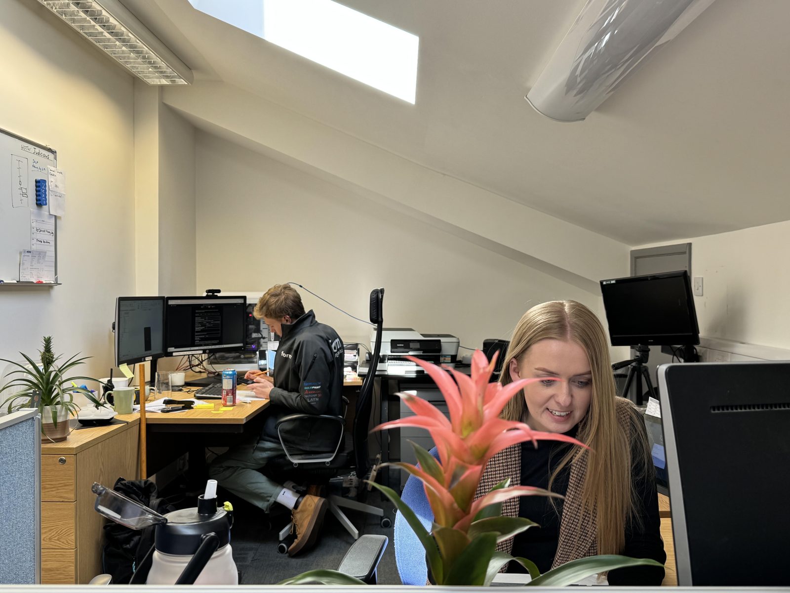
Real people, a real workshop
No call centre and no middlemen. When you contact TCI Construction, you speak to the team who design, build and check your mould.
 Thomas LaneManaging Director
 George PrestonDesign & Project Manager
 Kelly BallingerHead of Partnerships
 Jim AndertonProduction Manager
 TheodoreEmployee Welfare